
When this mosfet TURNS on. this coil create a magnet field
and when this mosfet is off. this energy pushing the volt in to the output capacitor.
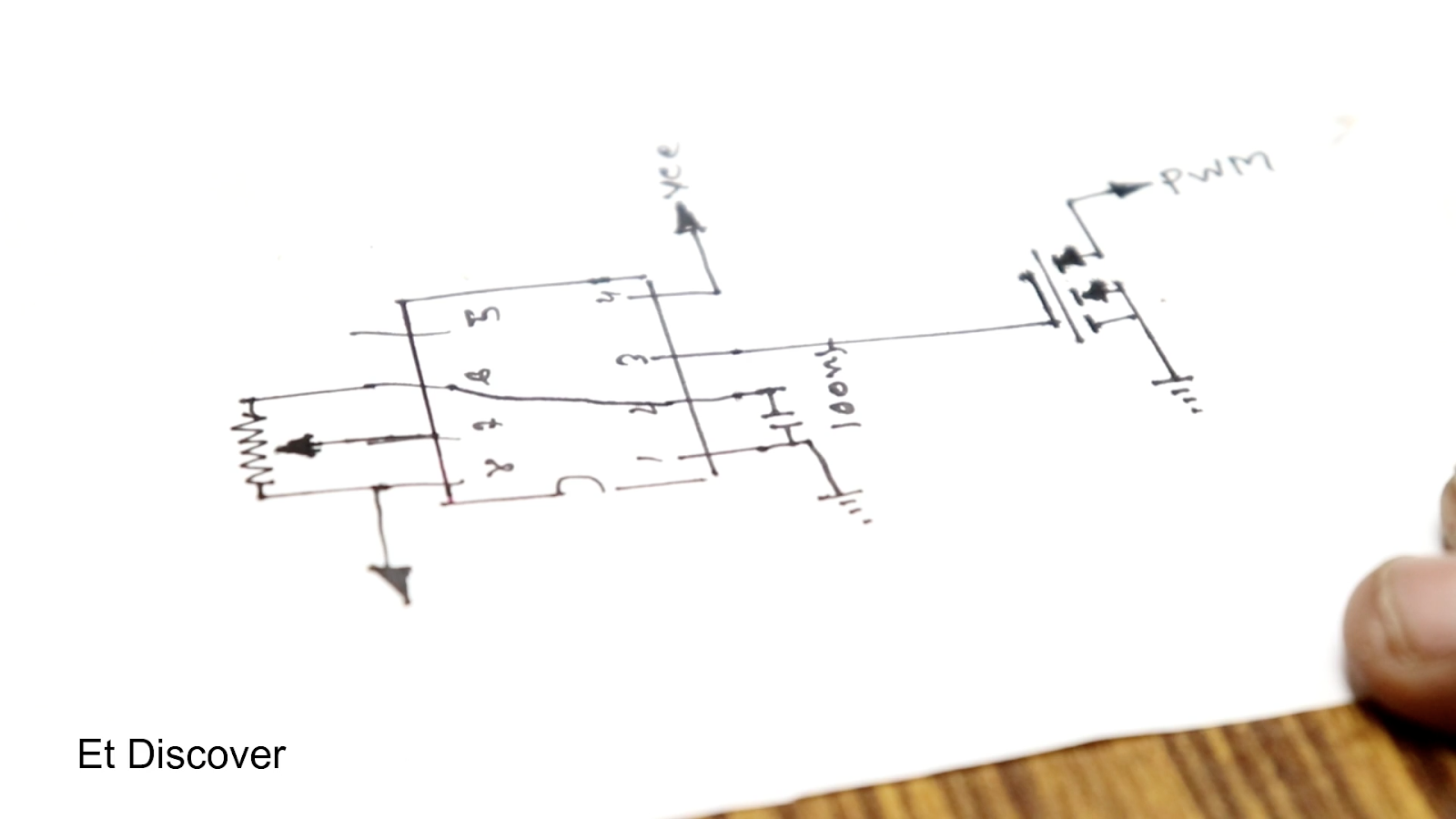
the output voltage depends on how fast the mosfet will turn on and off.

This digram for pwm signal.
555 timer ic is good for it.
Which can create 20 to 50 hz signal.
which comes out from this 555ic’s 3 no pin.
this depends on this 10k tremer.
i connect this led strip to the end of my boost converter.
and in the in put i connect the lithium battery 3.7 volt.
and its working.

diagram

full video link


Good.
ReplyDeleteAwesome bro!
ReplyDeleteCan I use IRF740 mosfet?
ReplyDeleteYes
DeleteThis comment has been removed by the author.
DeleteCan this circuit use for 24v of dc motor?
Delete12v input ?
DeleteYes
DeletePlz mention all component
ReplyDeleteWhich capacitor is in this video because you not mention capacitor number
ReplyDeleteIn YouTube video comment, he mentioned it as 220uF 50V
DeleteI have the parts listed as;
Delete10k variable pot
100nf cap
555 timer
221 Inductor
IRFZ44N
1N4007 Diode
220uf 50V Radial Cap
Is that right?
Can a different size Radial Cap be used?
Can I use 13007 transistor?
Deletei can see that the capacitor is 100uf / 25V .. Man your near 40V output then the capacitor you used is 25V.. come on.. but any way nice work it is just some minor issues you need to correct there
ReplyDelete50 volt
DeleteCan we use 25 Volts
DeleteNo if you raise the voltage beyond 25 v capacitor will blow out
DeleteIt's a digital joule thief
ReplyDeleteYeah obviously joule theif is a buck converter only
DeleteIs it 220 mili Henry or micro Henry plss reply....
ReplyDeletemicro Henry = 220uH
Deletecan i use different code of inductor?
ReplyDeleteEl diagrama no es claro
ReplyDeleteI use 220uH inductor
ReplyDeleteCapacitor :22uf /400Volts
MOSFET :2kS3714 N-channel
Diode :IN5822 Schottky
Then ,the circuit produce 56Volts Output .Applied input voltage is 3.7Volts.
Can I see your circuit please?
DeleteWhere you find 220 uh inductor, or can be replace with any inductor?
DeleteCan use this circuit for vapor..
ReplyDeleteplz. mention where to connect 4.7k resistor. this info is not mentioned in diagram
ReplyDeletebro where you use 4.7k resistor you will not show in circuit diagram
ReplyDeletethen onto the next or on the off chance that you need to purchase cash too particularly in. online audio converter
ReplyDeleteI tried to make design in proteus it showing same input n ouput
ReplyDelete29 August 2019 at 14:47
ReplyDeleteI have the parts listed as;
10k variable pot
100nf cap
555 timer
221 Inductor
IRFZ44N
1N4007 Diode
220uf 50V Radial Cap
Is that right?
Can a different size Radial Cap be used?
Very nice
ReplyDeleteI don't understand why there is a resister in your working prototype but not in your diagram? What is the value of this resistor and where does it connect in the circuit ?
ReplyDeleteIf you really want to help us out, please post the BoM (bill of materials) and a clear schematic. Thank you!
ReplyDeleteHello Brother! I want to know that where should 4.7 k resistor connect?
ReplyDeleteplease reply waiting for your kind response.
Va en el (gate) del MOSFET
DeleteHow much ampere this circuit out
ReplyDeleteapakah bisa selain z44.. misal tip41
ReplyDeleteapakah bisa selain z44.. misal tip41
ReplyDeleteHow to make Nokia battery good power bank
ReplyDeletehellow bro i am in class 8th i want try this pls say is thisis working pls
ReplyDeleteCan i use 5 volt for input?
ReplyDeleteCani i use 5 volt for input?
ReplyDeleteCan i use 5 volt for input?
ReplyDeleteThs circuit definitely not gonna work , They posted different circuit here.
ReplyDeleteYes,
DeleteI think simulation results are also unsatisfied.
If I connect load boost converter doesn't work and output reaches equal to input voltage ... anybody tell me what happens? Pls.
ReplyDeleteNot work! When connect 12v led bar flash 0.001 second and the output voltage drop.
ReplyDeleteThe resister is not in diagram as like in video
ReplyDeleteWhere is the resistor or inductor in the diagram?
ReplyDeletedoes the 470 ohm resistor go from output of 555 to gate of mosfet.
ReplyDeletecopy permission thanks
ReplyDeleteHELLO GOOD AFTERNOON, CAN YOU HELP ME WITH MY DAUGHTER'S XV PROJECT, SHE WANTS A LAMP THAT TURNS ON BY ITSELF AND PLAYS A HARRY POTTER MELODY, BUT THE LAMP ONLY GIVES 3V OUTPUT AND I NEED 5V TO CONNECT A SMALL MP3, THIS BOSTER CAN IT ONLY HANDLE 5V? OR WHAT CHANGES WILL I NEED FOR THIS VOLTAGE? IN THE DIAGRAM IS LEG 5 N CONNECTED TO NOTHING, RESISTANCE, CAPACITOR OR GROUND? THANKS, I REALLY NEED HELP, WITH A VERY SIMPLE BOOSTER THAT I CAN MAKE WITH RECYCLED PARTS FROM CHARGERS, SAVING LAMPS AND OTHER DISCARDED APPLIANCES. THANK YOU FOR YOUR TIME TO REACH ME AND ALSO FOR EVERYTHING YOU SHARE. I USE GOOGLE TRANSLATOR
ReplyDelete